S *m*e*n*u | 241
-
|
-
- Video #656
A Introduction
(this page)
- (9L11).
|
-
[an error occurred while processing this directive]
|
-
Drawings
below on this page:
-
Fig 1
S-gauge Wiring Sketch
[below]
-
Fig
2 G-scale Equivalent Wiring Diagram [below]
|
|
A. Comments
1. Overview:
The
video (link is in the menu to left), made by
Mark Anderman of the Susquehanna S Gaugers, at
the April 2007 "Steamup" in Williamsport Pa,
shows a demonstration of an automatic control
system they made to operate 3 American Flyer
trains on one circle of track, using all stock
AC Gilbert parts. They used a siding to hold 2
trains, plus a 3rd block operated by a
semaphore on the mainline.
2. All Stock AF
Parts:
The
system shown in the above S-gauge video uses
all stock Gilbert parts. The converging switch
is used as a relay to control the 2 siding
blocks, and a Gilbert semaphore controls the
3rd block in the mainline. They used the
pressure-sensitive Gilbert track trips to
control the switches and the semaphore.
|
|
B. Remove The
3rd Block ?
We
believe this system could probably be modified
by removing the block '3' in the mainline, and
using just the 2 blocks in the sidings. The
semaphore would control power to the sidings
If you can
visualize. at about 2/3 of the way around
the loop, the train on the mainline would
pass over at 'T2' (green) track trip, which
would "release" one of the trains parked on
the sidings, thus maintaining spacing
between trains, but without using the 3rd
block on the mainline --see Figure 2 below.
This scheme is
demonstrated in the largescale Video #1 "How
It Works" which shows the same arrangement
in largescale -- links given above in Para.
2. Notice the operation is a little
SMOOTHER, because when you remove Block 3,
then trains don't stop on the mainline.
The Wire That
Used To Go To Block 3
On the
S wiring diagram, you would remove Block 3.
You would take the wire that previously ran
from the semaphore to Block 3, and instead
route it to switch M2. When the semaphore is
red, no power would go to either of the siding
tracks hooked to to switch M2. When the
semaphore changed to green, the power would be
routed to whichever siding switch M2 is
aligned to. .... make sense ?? No? Try
watching the G-scale video.
|
C. Comparing
The 2 Drawings
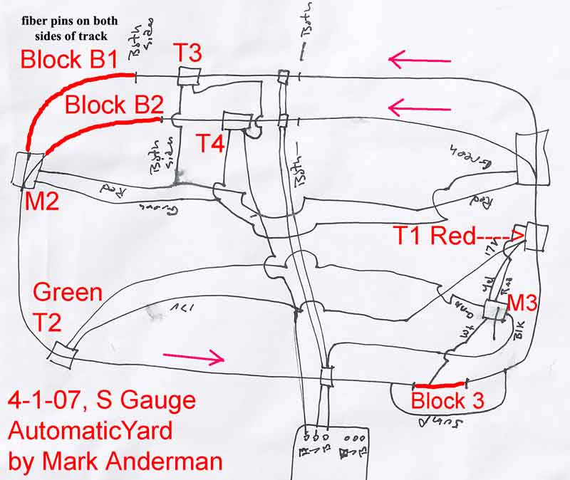
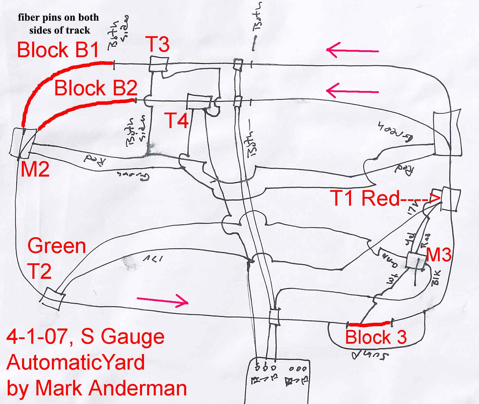
Immediately
below
is shown the S gauge wiring diagram by Mark
Anderman (notes in red were added by James
Ingram). Following the S drawing, is the
G-scale equivalent drawing.
Components
Numbered Same On Both Drawings
"Stop
blocks" B1 and B2 -- These appear on both
drawings, in the sidings. 'Block 3' on the
S-gauge drawing does not appear on the G scale
drawing, because the 3rd block is not used.
Track trips
T1, T2, T3, & T4 -- On the S drawing,
these are stock Gilbert pressure-sensitive
track tricps. On the G drawing, there are
stock LGB reed switches activated by magnets
on the bottom of the loco. They both
accomplish essentially the same result --
they send an electrical pulse to throw a
switch or relay when an engine passes over
them.
Relay 'M3' --
On the S drawing, this is the Gilbert
semaphore. On the G-scale drawing it either
an LGB semaphore, or an LGB DPDT relay.
Relay 'M2' --
this routes power to 1 of the 2 sidings. On
the S drawing, it is a Gilbert switch, which
has relay capability built into it. On the G
drawing, it is an LGB relay.
|
|