*m*e*n*u | Ingram Autocontrols
-
*m*e*n*u | Ingram Autocontrols
-
|
-
-
-
|
Contents
below on this page:
1. Overview Of These Controls [below]
2. Advantages/Disadvantages Of These
Electro-Mechanical Controls
[below]
3. The Three Systems On This Website
[below]
4. Examples Of Layouts Using These Systems
[below]
5. How These Controls Work
[below]
6. History of Automated Displays
[below]
7. Comments About Reliability - Indoor Operation
[below]
8. Comments About Reliability - Outdoor Operation
[below]
9. Suggestions for Getting Started
[below] |
-
Comments
About Updating This Website
- I
periodically update parts of this
website, as time permits.
- I did
the bulk of the actual
experimenting-with and writing-about
these controls from 1986 to 1996.
- From
1992 to 1997 I marketed drawings,
laminated templates, videotapes, and
some assembled units.
The
marketing effort ceased back in 1997, so
please ignore all references to items
for purchase. Any questions, feel free
to telephone me using the contact link
at the bottom of the page.
|
Comments
About LGB Going Out Of Business
Finding
the LGB parts to build these LGB systems
can be difficult,
as a result LGB ceasing production in mid
2007.
|
-
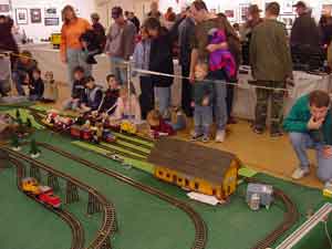
Add the
enchantment of an automatic yard to your
display layout
|
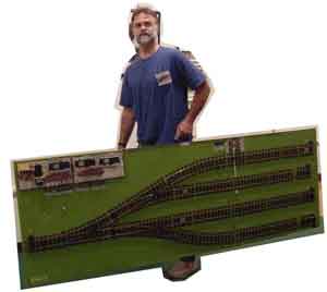
Website
operator James Ingram demonstrates 4-track
automatic yard "to go"
|
-
1.
Overview Of These Controls
Subject Of
This Website
This
subject of this website is the operation of
G-Scale, automatic model railroad controls.
The function
of these controls is to automatically
control multiple trains on the same track.
This website
contains photos and Quicktime web video,
that show these controls operate. It
includes plans that you can use to build
these control units.
Purpose of
These Controls
The
three Automatic Train Control Systems
described in this bulletin give you the
capability to operate multiple G-scale
trains on the same track. These controls are
fully automatic -- they
control slowing-down, stopping &
starting the trains, plus they control
switches and signals -- you just sit back
and enjoy. No modifications
to locomotives are required except adding a
magnet to the bottom. They use simple
off-the-shelf LGB switch motors and LGB
snap-in relays.
To the best
of my knowledge, these Ingram Autocontrols
systems are unique in that they control
not only trains but also signals and
switches, use no electronics, and use
simple-enough technology such that you can
build them yourself. They
are powered by LGB switch motors, and
controlled by LGB track contacts which are
activated by magnets mounted on the bottom
of the locomotives.
They are
most suitable for indoor display
layouts but can be used on indoor
permanent layout, and also outdoor layouts
(see discussion below about outdoor
reliability).
|
-
-
2.
Advantages/Disadvantages Of These
Electro-Mechanical Controls
Advantages
(vs electronic controls)
Simplicity
People
often laugh in my face, when I claim these
controls are "simple". after they have
looked at the wiring diagrams. But they
are simple compared to electronics. If you
can visually water flowing through a
garden hose, in the same manner you can
visualize current flowing through a wire
between the LGB reed switches and the LGB
switch motors.
Parts
Availability
Since
the parts are from LGB (except rheostat
& toggle switches), you don't have to
worry about some electronic manufacturer
going out of business, and leaving you
with an electronic board that nobody can
fix.
Repairing At
Shows
You
can repair any problems with these units,
if you can replace an LGB switch motor or
a reed switch. At a train show, this is
useful to be able to fix the unit yourself
if something malfunctions, versus having a
malfunctioning electronics box that nobody
at the show can fix.
Initial
Conditions
Since
all "states" of the controls are indicated
by the "arms" of the LGB switch motors,
you can both see and set initial
conditions by observing and moving the
"arms".
DC or DCC
These
controls work for standard DC engines.
They should also work for DCC engines, by
adding a 2nd rheostat to allow separate
control of the voltage in the "startup
block". (I have not yet used Largescale
DCC engines with these controls, but I
hope test them soon. Tests running
decoder-equipped S-gauge engines through a
rheostat-controlled block, indicate that
the controls will work with
decoder-equipped engines.
Disadvantages
(vs electronic controls)
Cost
-- The LGB parts are generally much more
expensive, compared to buying generic
electronic components.
High Cycle
Reliability -- On a permanent indoor
layout where the controls are operating
continuously -- a restaurant for example
-- the electrolmechanical parts may not
last as long as solid state electronics.
|
3.
The Three Systems On This Website
This bulletin
describes three systems for controlling
multiple trains on the same track:
System 1 --
Single-Track Experimenter's Block
This
system can operate up to two trains per track.
System 1 -- Single Track Automatic Block
System 2 --
Double-Track Automatic Switching Block
This
system can operate up to three trains.
System 2 -- Double Track Automatic Switching
Block
System 3 --
Four-Track Zellner Yard
Zellner
Yard is an expansion of the 2-track system.
Zellner Yard can operate up to five trains by
itself. Assisted by a single-track block, it
can operate 6 trains. The plans show you how
build it in stages of 1 track, then 2 tracks,
then 4 tracks.
Zellner Yard
uses the same control unit as the 2-track
sytem, plus a 'helper control unit' to
control the additional two tracks.
System 3 -- Four-Track Zellner Yard
|
-
-
5.
How These Controls Work
How The
Logic Works
All
three of the systems described on this
website use the simple concept of stopping
trains in a yard area (one, two, or four
tracks) until a train on the mainline
travels about 2/3 of the way around the
loop; then they "release" a train from the
yard.
The Logic
Diagrams
page explains how several variations of
these controls operate.
How The
Hardware Works
You
can build and modify these systems
yourself from available plans. The plans
include a laminated, colored, full-size
"template" upon which you build the
control. The template shows all parts
locations and wiring paths in color for
easy assembly and complete documentation.
These
controls use multiples of simple on/off
circuits with no electronics. Magnets on
the bottom of the engines activate reed
switchs which control relays. The relays
turn on and off the DC current flowing
to insulated "blocks" in the track.
Too Many
Wires? The biggest criticism you hear
about these block-type control systems
is that they use too many wires. You
might compare them to a Christmas tree
light system -- admittedly a few wires,
but each one has a simple,
easily-traceable function.
The
locomotives require no receivers or
decoders -- only a magnet on the bottom.
No electronics are involved -- these
systems are low-tech electromechanical
-- consisting of off-the-shelf LGB and
Radio Shack components. They require no
special skills to construct, maintain,
or operate.
|
6.
History of Automated Displays
A
Semi-Accurate History of Automated
Controls
For
years, model railroaders have been
constructing their own track, locomotives,
cars, power packs, buildings, bridges,
etc. However the concept of constructing
automatic controls to operate multiple
trains on the same track, though
fascinating, seems to be a relatively
unexplored area. The small number of
people interested in simplified automatic
controls is probably best evidenced by the
relative lack of coverage you find in the
mainstream model railroad press on this
subject.
Automated
Display Layouts
Model
railroad display layouts have generally
operated only one train per track, with
the exception of a few sophisticated
museum-type layouts:
- CA,
Sacramento the Underground Railway in
HO
- FL,
Orlando the Orlando Toy Train Museum
in G
- IL,
Chicago the Museum of Industry and
Science in 2 rail O
- MD,
Baltimore the Baltimore and Ohio
Museum in HO
- PA,
Pittsburgh the Buell Planetarium in 3
rail O
- PA,
Strasburg the Choo Choo Barn in 3 rail
O.
Enter
Ingram AutoControls 1988
In
1986, James Ingram developed a simplified
modular automatic block using
off-the-shelf LGB and Radio Shack
components, with a very elementary wiring
circuit, which provided another way to
control multiple Largescale trains on the
same track. He started distributing these
publications, using the name "Ingram
AutoControls".
These
portable modular control units have been
refined by using them on public
displays, where the whole layout --
automatic controls and all -- has to be
transformed from bare concrete floor to
operating railroad in a matter of hours.
In 1988
the first of many publications (P8811)
was written. In 1992 the first of many
U_BLD_M Drawings were drawn.
A two
month around-the-clock effort in 1992
produced the one-of-a-kind Ingram
Autocontrols videotapes, which
extensively demonstrate these simple,
but little-used techniques of
multi-train control. In 1996 the
newly-constructed 4-Track Zellner Yard
operated 5 trains on one track at the
12th National Garden Railway convention
in Orlando.
Exit Ingram
AutoControls 1997
From
1992 to 1996 about 20 or so control units
were assembled and shipped. However,
advertising expenses were many time more
than the small profit that could be
generated by building labor-intensive
control units on a "one-by-one" basis.
Thus this sputtering "manufacturing
effort" more or less ground to a halt in
1997. However, this website makes possible
the distribution of the plans.
|
7.
Comments About Reliability-Indoor
Operation
Possible
Malfunctions That Adversly Affect
Reliability
You
may encounter some of the following
problems that can cause these automatic
block systems to malfunction:
- Engine
stalls or slows down, upsetting the
timing
- Rolling
stock uncouples or derails
- AC
Control Voltage is too low (see AC
Control Voltage comments in Section
4.4 More Details About Building
The Single Track Block)
- A track
contact sticks in the closed position.
- A relay
motor on the control unit or a track
switch fails to completely throw
The first
two problems are pretty much self
explanatory. The last two are described
in more detail in Section ___ Troubleshooting
in the Single Track Block's operating
section.
My Own
Experience On Indoor Displays
My
own experience consists mainly of
operating the controls on indoor displays.
On a good day, we can run a typical 3 loop
display for twelve hours, operating about
four trains on each loop, and have only
five or six crashes due to malfunction
controls. On a bad day, we will have a
track contact start to stick, and we will
start having a crash every ten minutes
until we shut the loop down, and replace
the track contact.
|
8.
Comments About Reliability-Outdoor
Operation
In
my opinion, the most trouble-prone spot on
outdoor systems, is the diverging switch
where trains enter the yard, since this
switch is exposed to the weather and tends
to eventually gum up due to outdoor dirt.
The LGB,
Radio Shack, Clarostat (rheostat), and
Shiloh Signals components are all
reasonably tolerant of damp conditions.
All 3 of the control units are designed
to be modular -- that is, you can mount
them directly on the track unit under a
weatherproof building. Or you can mount
the control unit remote from the track
unit next to the transformers, and
connect it to the track by using a
multi-wire cable.
|
9.
Suggestions for Getting Started
If you wish
to further pursue this concept of running
multiple trains on the same track, I offer
the following suggestions:
- Study the
Logic Diagrams, and view the videos.
- Construct
a simple single-track Automatic Block.
Plans for this are included on this web
aite.
The plans will walk you through
constructing a simple "starter version"
of the block with just an on/off block.
Later you can add the rheostat to create
the slowdown block as a 2nd step, then
signal lights as a 4th step.
All the parts you use can be "recycled"
to other uses, or used for more advanced
controls projects.
- Operate
this experimenter's block indoors on a
simple, temporary loop of track.
Experiment by duplicating some of the
demonstrations on the videos.
- After you
get comfortable with the Single-Track
Experimenter's Block, you may then want
to build the 2-Track Automatic Switching
Block, and eventually expand it to the
4-Track Zellner Yard.
|
This page originated
1997, modified 9/3/2009 by
(bottom include)
JamesRobertIngram.com
, Williamsport
PA, Apache Junction AZ
|