*m*e*n*u | Ingram Autocontrols
-
*m*e*n*u | Ingram Autocontrols
-
|
|
Logic
Diagrams
for The Three Configurations of Controls
All three
of the systems described on this website use the
simple concept of stopping trains in a yard area
(one, two, or four tracks) until a train on the
mainline travels about 2/3 of the way around the
loop; then they "release" a train from the yard.
Note that you
can build systems with number of tracks --
from 1 track to 4 tracks or more, using the
same basic logic.
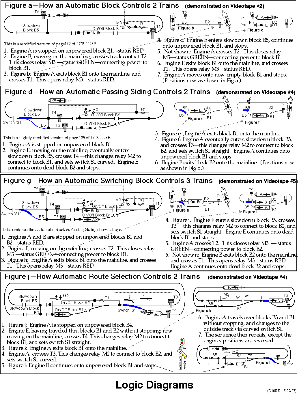
Fig a - One
Track - Automatic Block
Figure
a below shows the logic for a One-Track block
controlling two trains.
Fig g - Two
Tracks - Automatic Switching Block
Figure
g below shows the logic for a Two-Track
Automatic Switching Block, controlling three
trains.
Four Tracks
The
four-track Zellner Yard, is essentially an
extension of the two-track Automatic Switching
block, increasing the capacity from 2 tracks
to 4 tracks.
Zellner Yard,
at the moment, does not have a logic diagram
on this page. The "Sequencing Schematic",
the last
drawing
on the drawings page, shows part of the
logic.
Variations
Fig d - Two
Tracks - Automatic Passing Siding
Figure
d below shows the logic for a Two-Track
Automatic Passing Side, controlling two
trains. (If the block part of the Automatic
Switching Block shown in Figure G is shut off,
then it operates as an Automatic Passing
Siding.)
Fig j - Two
Tracks - Automatic Route Selection
This is
a variation of the Automatic Passing Siding.
It's not discussed any further on this
website, but is demonstrated in the
videotapes.
|
|


