A, Introduction

Model 401, 4-Track Yard (Largescale)

Latest control unit design is in the Model 402 drawings

Expanding from 2 to 4-Tracks - Description

*m*e*n*u | 401
* Model 401 *
(aka 1653/1654)

Video #644
A Introduction
B Key Drawings
C All Const Dwg
D All Oper Dwgs
E About The PDF's
 F Special Wiring

* PDF Directory

  Latest design is
  Model 402

Special 2-piece track unit wiring
  (12F17)

-
[an error occurred while processing this directive]


List of Drawings, shown BELOW on this page:

1. Overview
2. Related Sections
3. The Completed Unit
4. The Drawing Set
5. What The Drawing Set Produces
6. Expanding From The 2-Track Block to Zellner Yard
7. Other Ideas From Electrical Guru Ted Greeno

1. Overview

Summary

This drawing update set (added 1996) is used to expand the 2-track yard to a 4-track Zellner Yard.

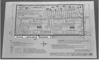
Sheet 39 "Helper Control Unit Template" has the layout to build a "helper" control unit, when when added to the 2-track control unit, will result in an expanded control unit that will control the 4-track yard.

When To Use The (Model 401) 1651 & 1653 Templates Described In This Section

If you already have a 2-track unit built, per the Model 1651 design described in the Model 205 drawings, then you can add the #1653 Helper Control Unit to expand from 2 tracks to 4 tracks, as described on web page ??F1, 4 Track Expansion.

When To Use The Model 402 Drawings

Use the newer Model 402 template (added May 2006), if you want to build a 4-track control unit from "scratch", rather than expanding a 2-track unit.

The Model 402 Yard uses most of the drawings from the earlier 1654 design (Sections C1 thru C4), but there are 3 new drawings created for the one-piece control unit: Cover Sheet, template, and parts list.


2. Related Sections

  • Section D1, (this section) 4-track Zellner Yard - Description
  • Section D2, 4-track Yard - Key Drawings
  • Section D3, 4-track Yard - All Construction Drawings
  • Section D4, 4-track Yard - All Operating & Reference Drawings
  • Section D5, 4-track Yard - All Drawings PDF - use this section for PRINTING

    This section makes reference to the following drawings, which can be viewed in the next section, KEY drawings:

    Drawing #35 -Track Unit
    Drawing #38 - Track Wiring
    Drawing #39 - Template For Helper Control Unit
    Drawing #41 - Parts List & Costs For Helper Control Unit
    Drawing #42 - Parts List & Costs For Track Unit
    Drawing #46 - Signal Light
    Drawing #49 - Schematic
    Drawing #50 - Sequencing Schematic


3. The Completed Unit

In January 1996 we developed this design that expands the Model 165 Automatic Switching Block from 2 tracks to 4 tracks. This 4-track unit is named "Zellner Yard" -- for the reason that these multi-train megadisplays we have been doing the last 5 or so years, were always dependent on having Ed Zellner and a fleet of his trains available to wear out.

The following figure shows the completed 4-Track Zellner Yard.

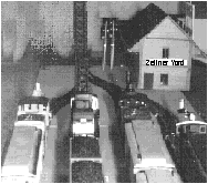
Orlando, April 1996 -- 7 of Ed Zellner's trains entertain visitors on this 10x20 display at the 12th National Garden Railway Convention. 4-track Zellner Yard controls 5 trains on the elevated loop. Single-track Block controls 2 trains on the inside loop.

Figure 1 - 4-Track Zellner Yard
Zellner Yard operates in the normal switching block manner, except instead of holding 2 trains in the yard while the 3rd train is on the mainline, it holds 4 trains in the yard while the 5th train is on the mainline.

It automatically controls the switches, target lights on a special Shiloh Signal's 6-light signal, plus slowdown, stopping and starting. Trains enter the yard starting on Track 1 on the left, and sequence across to Track 4 on the right.

Sheet 49, Schematic, and Sheet 50, Sequencing Schematic show how track power is sequenced from one siding to the next.


4. The Drawing Set

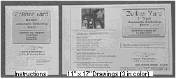
Item 9 -- U_BLD_M Drawing Set for 4-Track Zellner Yard


11"x17" drawings, step-by-step instructions, 3 color drawings (schematic, helper control unit template, & track unit wiring) plus a laminated color copy of the Helper Control Unit template


This drawing set expands the Model 165 automatic switching block from the 2-track built per Item 5, to the 4-track Zellner Yard version, in 3 incremental phases:

Phase 1, Single Track Unit
Phase 2, 2-Track Unit
Phase 3, 4- Track Unit.

Figure 2 - Drawings For Zellner Yard
Item 9 includes:
  1. Instructions, 8-1/2 x 11 -- 54 pages -- keyed to the drawings -- of step-by-step written instructions.
  2. Drawings, 11" x 17 -- 20 sheets -- including photographs, overall assembly, track unit dimensions, track unit wiring, parts lists and costs, Sheet 39 -- Full Size Pattern for Helper Control Unit, plus check-out, initial conditions, and operating sheets.
  3. Colored Copies of Key Drawings, 11" x 17:

    • Sheet 35, Track Unit Wiring

    • Sheet 39, Full Size Pattern for Helper Control Unit

    • Sheet 50, Schematic.

  4. Template -- Colored, plastic-laminated copy of Sheet 39.

The template is designed to be glued to the wood base of the control unit. For easy assembly, all parts and wires are shown full size in their proper location. You just place the parts and run the wires over top of their outlines.


5. What The Drawing Set Produces

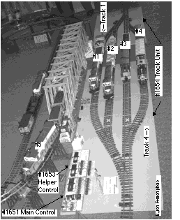
Zellner Yard uses a standard #1651 Control Unit (built per Item 5) that operates tracks 3 and 4 in the normal manner. The #1653 "Helper" Control" (built per drawings Item 9) is "slaved" to the #1651 control, and operates the two additional tracks 1 and 2.

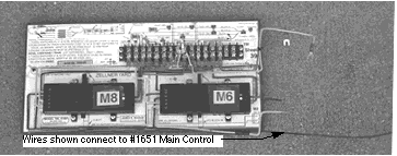
#1653 Helper Control Unit

The following figure shows the #1653 Helper Control Unit.
  1. Dimensions 6" x 13" x 3-1/2" high.
  2. Works with the main control unit (Figure 8) to operate the additional 2 tracks for the 4-track Zellner Yard.
  3. Has an on-off toggle switch. When toggle switch is off, the helper control unit is depowered, and two of the four tracks remain parked.
Figure 3 - #1653 Helper Control Unit
• Template Drawing on Sheet 39
• Parts list on Sheet 41
Works with the main control unit (Item 6) to operate the additional 2 tracks for the 4-track Zellner Yard.

Has an on-off toggle switch. When toggle switch is off, the helper control unit is depowered, and two of the four tracks remain parked.

#1654 Zellner Yard Track Unit

The preceding Figure 10a shows the #1654 Zellner Yard Track Unit
  • Track unit layout on Sheet 35
  • Track unit parts list on Sheet 42
  • Track unit wiring on Sheet 38.


6. Expanding From 2-Tracks To The 4-Track Zellner Yard

If you are presently building a 2-Track Automatic Switching Block, and think that in the future, you may want to expand it to 4-Track Zellner Yard, please refer to Item 9 the 4-Track Zellner Yard drawings before you start laying out the track. Item 9 guides you through setting up the system in the following steps:
  1. 1 track -- using just the #1651 Control Unit and Track 3 only.
  2. 2 tracks -- using just the #1651 Control Unit and adding Track 4. The yard area with 2 tracks, but designed for future expansion to 4 tracks, would appear as shown in the following figure.
  3. 4 tracks -- by adding the #1653 Helper Control Unit and adding Tracks 1 and 2.
x
Fig 10d -- Two tracks laid out for future expansion to 4 tracks

Parking 2 Tracks

An optional toggle switch "K3", can be used to depower the Helper Control unit when desired. In this mode, the trains on tracks 1 and 2 remain parked and never move. Meanwhile the main control unit (Item 6) continues to operate 3 trains in the normal Model 165 mode -- using tracks 3 and 4 via track contacts T3 and T4.


7. Other Ideas From Electrical Guru Ted Greeno

The sequencing logic for this 4-track yard is adapted from drawings made by Ted Greeno of Fontana CA sometime around 1990. The 5-track automatic passing siding you saw in operation on videotapes 1 and 6 (V9202), built by Tom Flynn of Louisville CO, is based on these Ted Greeno drawings.

Ted Greeno is one of the leading creators of designs and drawings for all kinds of G-scale automatic control schemes -- multiple trolley systems, reverse loops, switchbacks, mainlines crossing mainlines, etc, etc. An updated copy of his booklet "LGB Electrical Clinic" will be available sometime in the future. If you have any particular design needs, you can contact him at: 8164 Sewell, Fontana, CA 92335. His phone is 909-829-0873, if you don't mind him returning calls collect.


This page created 4/97, modified 12/7/2009 (20F17) by (bottom include)
JamesRobertIngram.com , Williamsport PA, Apache Junction AZ