*m*e*n*u | 402
-
-
*G *m*e*n*u-09i | Plans-IAC
-
|
|
Model 402 vs earlier Model 401:
This Model 402 is almost
the same as the earlier Model 401. The only
difference is that the Model 402 control unit is
built with all 4
switch motors on 1 template (base), whereas
the Model 401 was designed as an expansion
of the Model 205 2-track unit, and thus uses 2
separate templates (bases). Compare Photos
4 and 5 on this page to see the difference.
After browsing these 3
Model 402 pages, you can browse additional drawings
in the Model
401 pages. Note a lot of the text in the
401 pages, is discussion on how to expand from
2-tracks to 4-tracks.
|
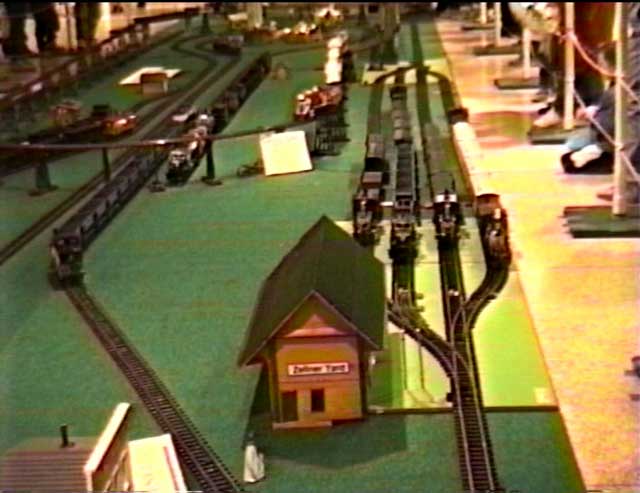
Photo 1 - 4-Track Automatic Yard.
built in 1996, operating in Denver Co, Feb 1996.
This photo was "screen captured" from the Quicktime Video
#2.
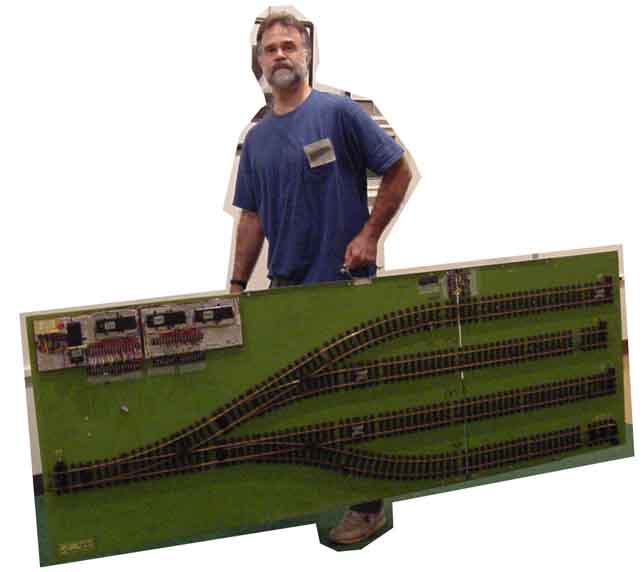
Photo 2 - 4-Track Automatic Yard
"to go". Designer James Ingram is shown carrying the
Zellner Yard 4-track system, ready to begin setup at the
Toy Train Expo, Williamsport Pa, December 2001.
The white control units are visible
in the upper left corner of the green board.
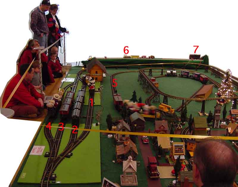
Photo 3 - The same 4-track Zellner
Yard in operation. Note trains 2, 3, and 4 sitting in the
yard.
Train 5 on the mainline has just "released" Train 1, shown
exiting the yard.
Train 5 will enter the yard on the empty Track 1. Train 1
will later "release" Train 2, and so on.
Note Train 6, the S-gauge S Helper Server switcher, with
Soundtraxx DCC,
is being automatically controlled point-to-point by the
386 laptop computer at right, Item 7.
(See the S Gauge DCC Computer
Control page for more
details.)
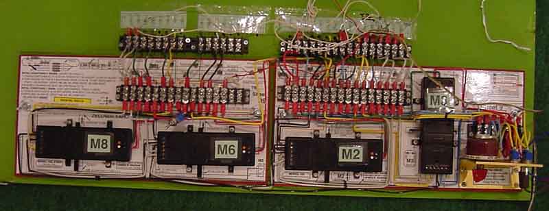
Photo 4 - Closeup of of control units.
Note that the base is a laminated, colored template
that shows all wire paths and hookup wiring diagrams.
The drawings for these templates are included on this
website.
Note this 1996 design uses the
original 2-track template shown on the right, and a
"helper control unit" shown on the left, in order to
create a 4-track control.
Photo 5 - This 2006 Model 402 template
design puts all the parts on 1 large template.
MPEG Movies - showing the
above 4-Track Unit
- MPEG
Movie 3 --
15 seconds, 320 pixels -- showing the above
4-track Zellner Yard in operation -viewed from
rear
- MPEG
Movie 4 --
15 seconds, 320 pixels -- showing the above
2-track Automatic Switching Block in operation
-viewed from front
- MPEG
Movie 5 --
60 seconds, 160 pixels -- showing the above
4-track Zellner Yard in operation -viewed from
rear
- MPEG
Movie 6 --
60 seconds, 160 pixels -- showing the above
2-track Automatic Switching Block in operation
-viewed from front
Note the general principle
of operation:
- The switching block holds
4 trains in the yard, until the 5th train on
the mainline "releases" one of the trains in
the yard.
- The train on the mainline
then enters the yard on the empty track.
- This sequencing continues
so all 5 trains take their turn running around
the layout.
|
This page created
May 2006; modified 12/6/2009 (20F17.) by
. .
(bottom include)
JamesRobertIngram.com
, Williamsport
PA, Apache Junction AZ
|