*m*e*n*u | 206
-
-
*G *m*e*n*u-09i | Plans-IAC
-
|

To view some ALTERNATE ways
of building these controls, see
Ted
Ansleys Flickr photo album, showing several
versions of indoor control units that he has built.
-
 This
Youtube
video by Tim Heffernan This
Youtube
video by Tim Heffernan
shows a Model 206 Control Unit, controlling an outdoor
railroad.
But keep in mind that DIRT getting in the turnouts, can be a
problem outdoors.
-
-
-
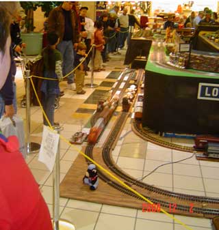
Photo 1 - A 2-track Automatic
Yard is shown operating on the Loose
Ties MRC
multi-gauge display, Dec 2006 in Selinsgrove Pa.
-
(If you care
about the details: Technically the above unit is a
model 205 Control Unit (aka Model 165) operating
on a Model 206 track unit. The below photos show
the new Model 206 control unit, which is almost
the same, except it has a 2nd rheostat, is a
slight narrower and longer.)
|
Purpose
Of
These Controls
These
2-track automatic yards seem to be the most
popular of the automatic controls (the others
being the single-track and the 4-track units).
These 2-track yards are typically used to
operate 3 trains on a single loop.
They seem to
be very effective at ENTERTAINING crowds on
display layouts like the one shown above.
Their simple electromechanical parts allow
most railroaders to understand how they
work, and keep them operating properly on
the display.
Principle
of
operation:
- The red block
holds 2 trains in the yard, until the 3rd
train on the mainline gets about 2/3 around
the mainline (wherever the T2 track contact
is positioned) and "releases" one of the
trains in the yard.
- The train on
the mainline then enters the yard on the
empty track.
- This
sequencing continues so all 3 trains take
their turn running around the layout.
|
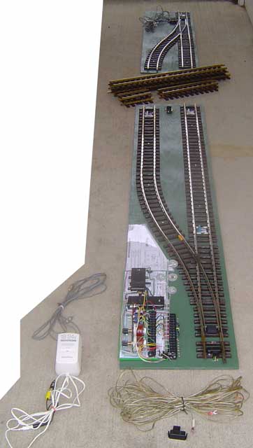
Photo 2 - Front view - Model
206 Automatic Yard -- plans drawn Feb 2007.
|
Components
To
Install In A Layout
The
above photo shows the yard and associated
components, ready to install in a display
layout.
- Track
Sections -- The front & rear track
sections (on the green plywood).
- Loose
Track -- The track shown between the
front and rear track sections, is used
to make whatever length of yard will
fit the layout space.
- Signal
Light -- The 4-light target signal -
shown already attached to the front
track unit.
- AC
Power -- The white box on the lower
left is a Radio Shack 18v/24v
transformer, used to provide 18 volts
AC power to the control unit.
- T2
Track Contact -- The small black
object on the lower right is the LGB
'T2' track contact, which is position
1/2 to 2/3 around the mainline. (The
T1, T3, & T4 track contacts are
attached to the front track unit).
- Rear
Switch Wire -- The duplex wire that
connects the rear switch to the
control unit is bundled up at the rear
switch motor.
|
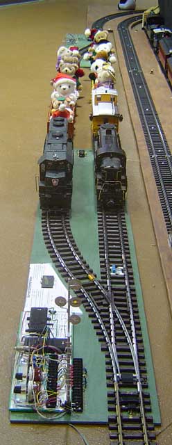
Photo 3 - Front view - Model
206 Automatic Yard.
A USA Trains GP-38 waits on the left siding, and an
Aristo Craft RS3 waits on the right mainline. An LGB
0-4-0 is the 3rd engine, out on the mainline on the
other side of the layout.
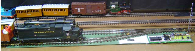
Photo 4 - Side View.
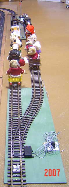
Photo 5 - Rear View.
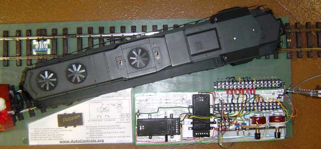
Photo 6 - Top View, showing the
GP-38 on the front switch.
Note the front switch has no motor. The trains just push
it into the correct position.
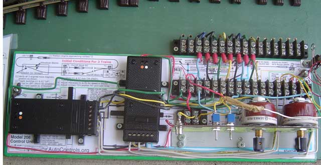
Photo 7 - Close-up of the
Control Unit.
Click
Here to view a LARGER
photo of the above assembled Control
Unit
Click
Here to view a LARGE photo of the
"template" that you see underneath the parts.
|
<
|
Template
Note
the control unit is built on top of a
"plastic-laminated template". This template
guides positioning of parts and wires during
construction, and provides built-in "hookup
documentation" and "startup documentation"
when the unit is in use on displays.
Components
The
primary components from left to right are
- LGB switch
motor M2 - routes power to either siding
or mainline
- LGB switch
motor M3 - turns power on and off in
startup block
- Blue toggle
switch K1 - controls power to switch motor
M2 (switching function)
- Blue toggle
switch K2 - controls power to switch motor
M3 (blocking function)
- Rheostat R1
- controls voltage in slowdown block
- Rheostat R2
- controls voltage in startup block.
Simplicity
The
advantages of these simple electromechanical
controls are:
- No
electronic circuits to malfunction, or
electronic vendors to go out of business
- The
throw-rods of the switch motors allow
operators to visually determine the
"state" of the control unit (siding or
mainline powered, stop block red or green)
- The
throw-rods of the switch motors allow
operators to easily set "initial
conditions" which the unit is started up,
or when it is depowered and just operated
as a "dumb track".
|
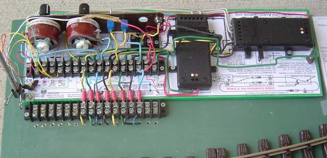
Photo 8 - View of the control
unit and template from the other side.
- The diagram in the lower left --
between the 2 terminal blocks -- shows the hookup
connections between the control unit and the track.
- The diagram in the lower right --
is an "initial conditions" sketch that reminds
operators how to start up the system.
Photo 9 - The "Initial Conditions"
sheet reminds operators how to start the unit up at the
beginning of the day's operations. The drawings have
additional instructions for powering down the siding or
the block or the complete controls.
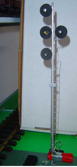
Photo 10 - The
Shiloh Signals ( ShilohSignals.com (website gone??) )
4-light target signal indicates all "states" of the
control unit.
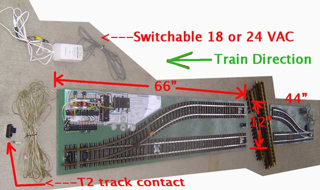
Photo
11 - Same photo as Photo 2 above, but rotated and
dimensions added.
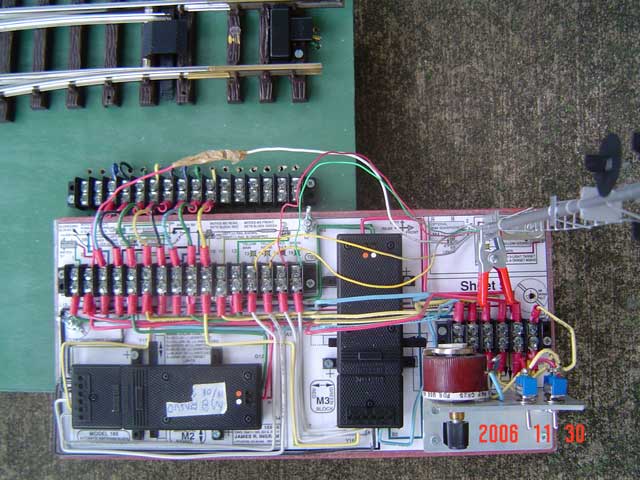
Photo 12 - This photo shows
the OLDER Model 205 Control Unit (aka 165).
The earlier Model
205 - drawn in 1994 -is almost the same, except it has
a single rheostat, and is a slight shorter and wider.).
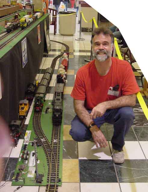
Photo 13 - Designer James
Ingram -- shown Dec 2001 with an early design Model 202
(aka Model 163), built in 1992.
-
|
MPEG Movies - showing
the above Model 202-Track Unit
Note
these OLD movies were made in 2003, before
the Quicktime videos were made
- MPEG
Movie 1
-- 15 seconds, 320 pixels -- shows above
2-track Automatic Yard
- MPEG
Movie 2
-- 60 seconds, 160 pixels -- shows above
2-track Automatic Yard
Note the
general principle of operation:
- The
switching block holds 2 trains in the
yard, until the 3rd train on the
mainline "releases" one of the trains in
the yard.
- The train
on the mainline then enters the yard on
the empty track.
- This
sequencing continues so all 3 trains
take their turn running around the
layout.
|
-
-
This page
created Mar 2007; modified 4/12/2010
(20F17)) by
(bottom include)
JamesRobertIngram.com
, Williamsport
PA, Apache Junction AZ
|