|
||||||
-
|
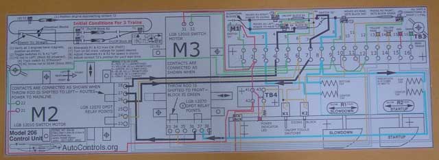
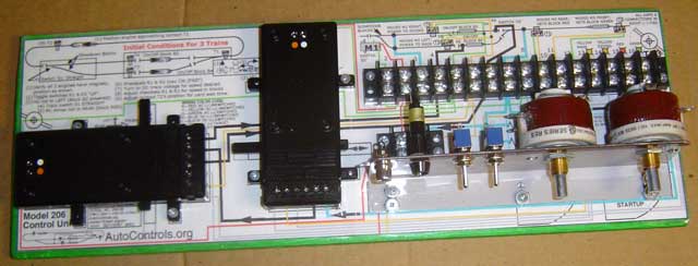
Photo 2 - Template cut from drawing
Sheet 9, plastic-laminated front and back.
I know this,
because I built my early pre-1994 units
without templates, and I am always having to
SEARCH for drawings to see how something on
them connects. With the template, you have
all the "hook up" information you need,
right on the control unit.
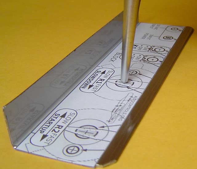
Photo 4 - You can use the drawing in
Sheet 9 Fig. 9.2 as a template
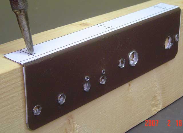
Photo 5 - You can use the drawing in
Sheet 9 Fig. 9.3 as a template
About The Angle You can use
the 1-1/2" x 1-1/2" x 1/8" thick aluminum
angle that you can find in the home stores.
Ideally you would like to cut the bottom
side from 1-1/2" down to about 1/2", so it
fits in the available space, and does not
cover the wires on the template.
Photo 6 - Rheostat bracket attached to base.
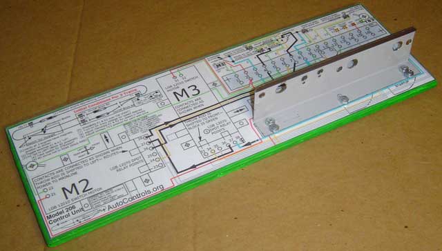
Photo 7 - Base with all parts
attached, ready to begin wiring.
About Wire
Gauges About Wire
Assembly Order Connect red,
yellow, & green (AC) wires 2nd. Connect any
red, yellow, green & blue wires that
connect to parts on the rheostat bracket
LAST. (If you connect these first, then you
have to "fish" the other wires underneath,
which is cumbersome.)
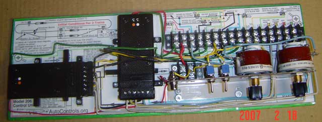
Photo 8 - Control Unit with all wires attached.
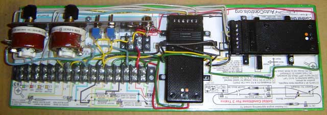
Photo 9 - Control Unit viewed from the other side
|
|||||