Page B, Overview

Model 206, 2-Track Yard (Largescale)

This is the LATEST design, done in Mar 2007

*m*e*n*u | 206
* Model 206 *

Video #655

A Introduction
B Overview
C Const Photos1
D Const Photos2
E Dwgs-Const
F Dwgs-Operate
G About PDFs

new
Yr 2020 Google Drive Album

 * PDF Directory

  Similar dwgs in
 previous
 Model 205 pages

(20F17)

-
*G *m*e*n*u-09i | Plans-IAC
* G Plans *

1 AutoControls Home

6 Plans Index
7 Museum
  (Previous Plans )
8 Special Parts
10 List of Videos

~~~~~~

 1-trk (Mdl 106)
 2=trk (Mdl 206)
 4-trk (Mdl 402)
 (20F17.)


Contents below on this page:

1. Related Pages [below]
2. Overview [below]
3. Logic Diagram [below]


1. Model 206 Pages


2. Overview

The Model 206 control unit drawing was made in February 2007. It is very similar to the previous Model 205 (aka Model 165) design, except for the following differences:
  • A 2nd rheostat was added, so there is now one rheostat for controlling voltage (speed) in the slowdown block, and a 2nd rheostat for controlling voltage in the startup block. This was done with the idea, that if operating DCC, the startup rheostat could be adjusted for full voltage, and the decoders could be adjusted for smooth acceleration.

  • This Control Unit is slightly narrower and longer (now 5"x14.5" vs 6-1/4"x13" previous model). When used with a 12" wide track unit, the overall width of the whole assembly is about 12-1/2", as compared with a 17" width for the previous model track unit -- see Photo 4 below.

  • The control unit is slightly lower, now about 1-3/4" high at the rheostat bracket, vs 2-3/4" high for the previous model. To cover it up, you might be able to use a loading dock instead of a building.


Photo 1 - Model 206 Control Unit


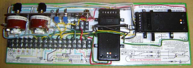
Photo 2 - Model 206 Control Unit - viewed from other side


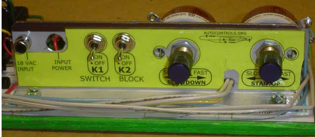
Photo 3 - Closeup of Rheostat bracket.
On this unit, the hole for the power-indicating LED has been left empty.
The lights on the Shiloh Signal's target signal can be used to indicate power -- see next photo.


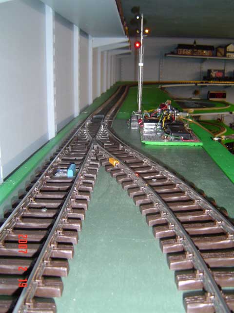
Photo 4 - Control Unit mounted on a Track Unit.
The whole assembly is about 12-1/2" wide.


3. Logic Diagram

The following figure, Logic Diagram for Automatic Switching Block, explains how this unit controls 3 trains on the same track. The operation is a combination of the Automatic Block and the automatic passing siding.


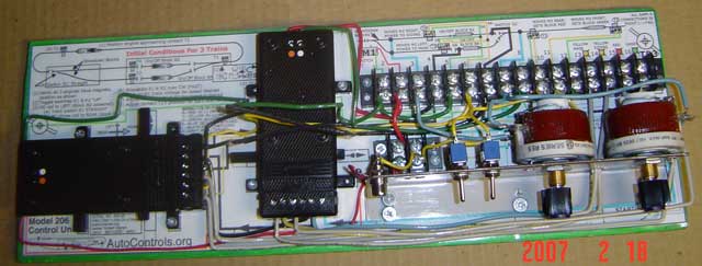
Photo 5 - Logic Diagram For 2-Track Automatic Switching Block


L This page created 2/22/07, modified 12/6/2009 (20F17.) by (bottom include)
JamesRobertIngram.com , Williamsport PA, Apache Junction AZ