*m*e*n*u | 206
-
-
*G *m*e*n*u-09i | Plans-IAC
-
|
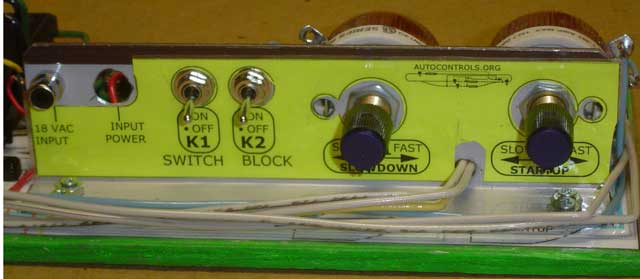
Photo 10 - Rheostat bracket with
label glued on.
The label was made using Sheet 9 Fig. 9.4, by printing it
yellow paper, then cutting it out and plastic laminating
it, then gluing it onto the bracket using a glue stick
On this unit, the hole for the
power-indicating LED has been left empty. The lights on
the Shiloh Signal's target signal can be used to
indicate power.
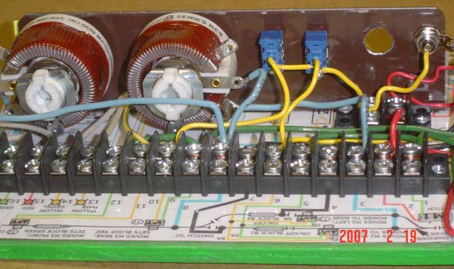
Photo 11 - Looking at the other side
of the rheostat mounting bracket.
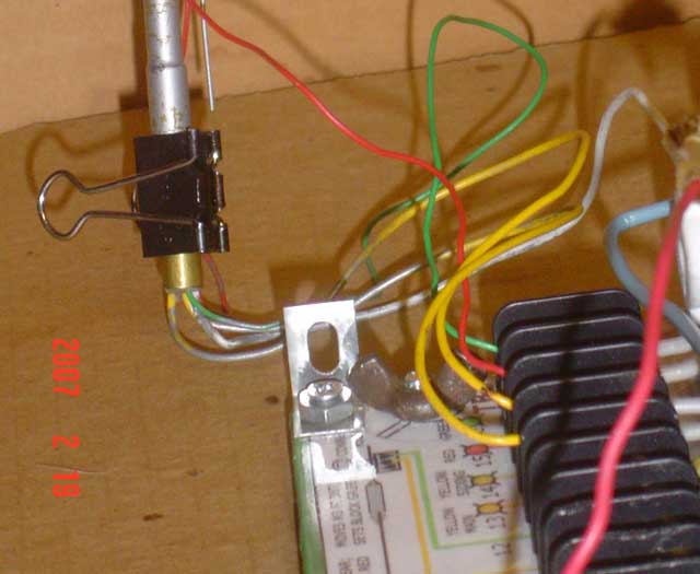
Photo 12 - A small angle (from an
old Gilbert erector set) mounted on the corner of the
base, allows the Shiloh Signals target signal to be
clipped to the base.
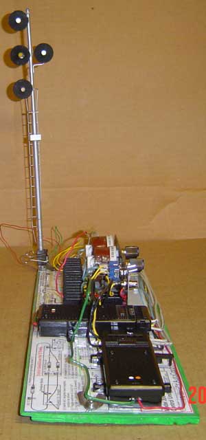
Photo 13 - The control unit with
the target signal attached.
(Since this unit is transported to displays, the signal
needs to be able to be laid flat against the base for
transporting it without damaging it.)
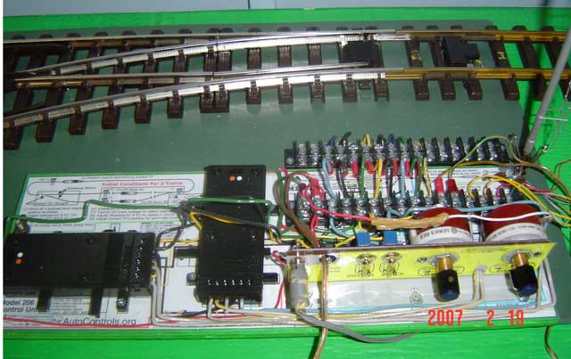
Photo 14 - The 16-terminal barrier
strip on the control unit,
matches up to the 16-terminal barrier strip on the track
unit.
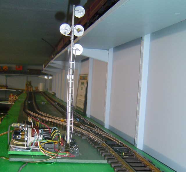
Photo 15 - Control unit and track
unit, viewed from the front.
Width is about 12-1/2".
And yes, I know that the wires connecting the signal to
the control could be shortened to be less SLOPPY,but I
keep them long, because this signal is moved around to
different units.
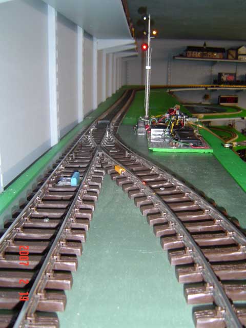
Photo 16 - Control unit and track
unit, viewed from the front.
|