-

C. Controlling 3 Trains

S Gauge, 2-Track Automatic Switching Block

<--  Back to  Intro Page

<-- Back to 2-Train-Control Page

s *m*e*n*u | 242
* Project 242 *

 Video #659
  2 trains
 
Video #660
  
3 trains

  A Introduction
  B 2-Trains
 
C 3-Trains

(9L13)

-
[an error occurred while processing this directive]
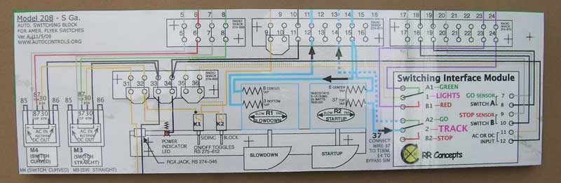
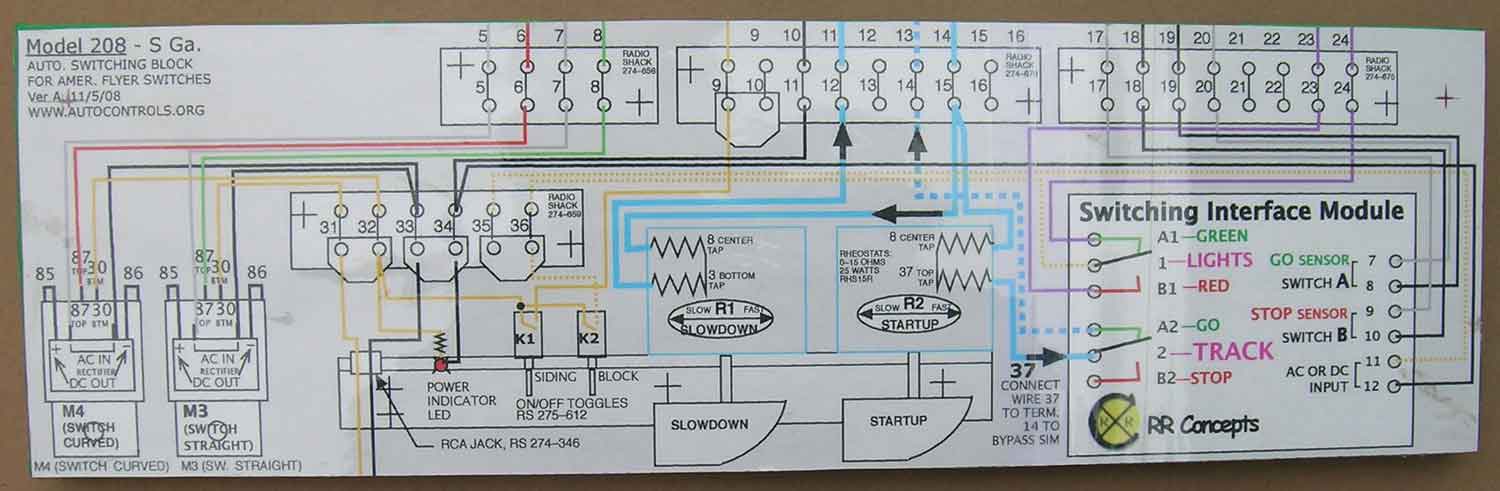
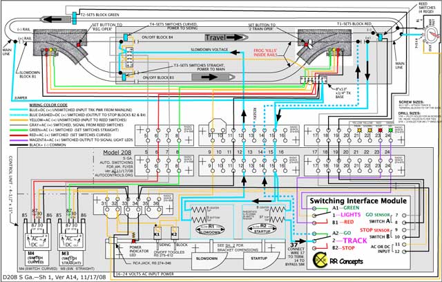
Drawings below on this page:
Fig 5. Wiring Diagram [below]
Fig 7 Logic Diagram For 3-Train Operation [below]


A. Comments

This 'Page C' shows the addition of a relay, to control 3 trains with the same track unit.  The relay used was a RR-Concepts 'Switching Interface Module' (aka SIM).

The logic is to hold 2 trains on the two 'yard' tracks, until the 3rd train gets about 2/3 of the way around the loop.  Then a reed switch changes the relay from "red" to "green", which releases the next train from the yard.

The logic diagram Figure 6 shows this operation.  It is probably easier to by watching Video #660, which shows this unit operating as a 3-train "Automatic Switching Block".  Note that the earlier Video #658 'Single Track Block' shows more details of the RR-Concepts 'Switching Interface Module'.


Figure 5 - S-gauge wiring diagram for 3-train operation
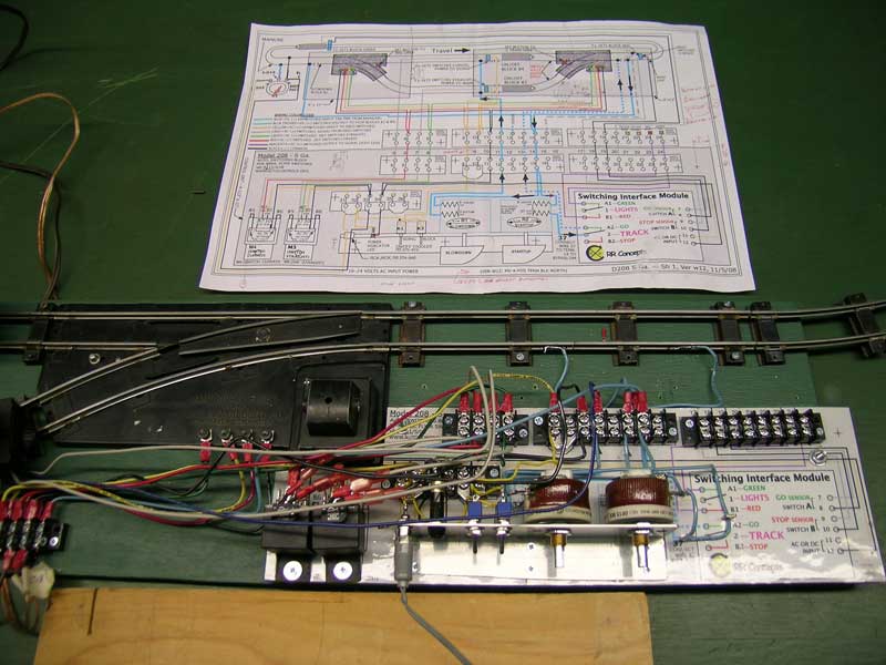
The RR-Concepts SIM (Switching Interface Module) is shown on the lower right.
[full size drawing]


Construction Notes regarding the above drawing

  • Info on the automotive relays is in the Google Photo Album  , and purchasing information is on the Anderman Flyer.com's "For Sale" page  {Page is gone}.
  • Details on the rheostats are on the Scarce Parts page (also colored wire info)
  • The rheostate mounting bracket uses the same drawing as an earlier largescale control -- see drawing at bottom of Sheet 9 Template for Model 206 largescale control unit.
  • You may want to browse all the Model 206 pages, particularly Photo 3 on the Overview page, showing the rheostat bracket, as construction is somewhat similar.
 

x

Photo 6 - "Template" -- Made using drawing from above Fig 5, plastic-laminated and glued to wood base,
ready to start adding parts
[larger version of base]


x

Photo 7 - Template shown in above photo, with parts added.  Note the "Switching Interface Model" -- which will go in the lower right corner of the control unit -- was not yet added, when this photo was taken.


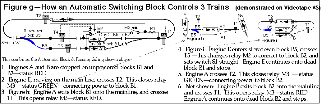
Figure 7 - Equivalent G-scale logic diagram.
This "logic diagram" was drawn for G-scale, but is also applicable to S gauge.

(There's a more detailed G-scale logic drawing
here, view 'Fig 12g' in the lower right corner of that drawing)
Note the relay identifed as 'M3' on the drawing, which is a RR-Concepts SIM (Switching Interface Module),
 
enables operation of a 3rd train, by holding both trains in the yard tracks, while a 3rd train is on the mainline.


This page created 1/28/09, modified 8/14/2016 (20F17) by (bottom include)
JamesRobertIngram.com , Williamsport PA, Apache Junction AZ