*m*e*n*u | 106
-
-
*G *m*e*n*u-09i | Plans-IAC
-
|
Sections
shown below on
this page:
-
-
1.
Summary
-
2.
Wiring Color Code
-
3.
Obtaining Colored Wire
-
4.
The Laminated, Modular Design
-
5.
Making Template and Bases
-
6.
Attaching
Parts - Control Unit
-
7.
Connect Wires - Control Unit
-
8.
Assembly Steps - Track Unit
1.
Summary
This
section outlines the steps required to
construct, in four phases; and then operate a
G-scale model railroad control device,
referred to as an "Model 146b Automatic
Block". This Automatic Block automatically
controls two trains (sometimes more) on the
same track, by keeping them separated from
each other by maintaining a predetermined
spacing.
|
Figure 1 - Model 146b Single-Track Experimenter's Block
2.
Wiring
Color Code
To make
it easier to follow the paths of the circuits
on the templates, all the wires are
color-coded, as per the following figure.
Each drawing
has the wire numbers and colors listed. If
you are using the black and white drawings
in this bulletin, I recommend you use a
colored pencil to color the wires on the
template. The circuits are 10 times easier
to follow after the wires are colored.
|
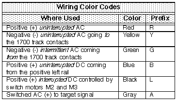
Figure 2 -Wiring Color Codes
3.
Obtaining
Colored Wire
I
recommend using solid, 18 gauge colored wire
to construct the control unit. Some people use
stranded wire and non-colored wire for the
control unit, but I advise taking this
shortcut. The solid wire you can shape better
to follow the paths, and the colors make it
much easier to understand how the circuits
work.
I also prefer
the solid wire because it easily screws to
the 17000 track contacts and 10153 isolating
track terminals, versus having to put the
50131 press cable connectors on the ends of
the stranded wire.
You can get
the 18 ga solid black, green, and red wire
from Radio Shack. The 18 gauge solid blue,
yellow, and gray colors is not available
from Radio Shack, but is still considered a
common product. Two manufacturers that make
these colors are Carol Cable and Apex wire.
See parts list on page 36 for the part
numbers.
You might be
able to find a distributor close to you by
calling these wire companies' headquarters.
Carol Cable has several numbers, in
Manchester NH at 800-424-5666, and on the
west coast 800-372-6374. Apex Wire is in
Hauppauge, New York, and their phone number
is 516-273-3322.
A distributor
here in Denver named Cashway Electric at
303-623-0151 (use the All-Wire part number)
handles the Apex wire, and they told me they
can ship it to out-of-town customers.
For "runs" of
longer than 30 feet (connecting to the
track), you may want to consider using a
heavier wire.
|
4.
The Laminated, Modular Design
What's A
"Laminated Template"?
The
control unit for this block is built on, what I
refer to, as a "laminated template", as shown in
the following figure.
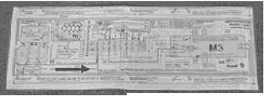
Figure 3 - Laminated Template For
Control Unit
|
The
laminated template is a full size drawing, with
all the wires shown in the proper color, that
has been plastic laminated. You glue the
laminated template to the wood base, and then
attach the parts right on top of the template.
Using the
template has the following advantages:
- Assembly is
easier, since you just attach parts and
wires right on top of the outline on the
template. There is no measuring or wondering
where anything fits -- it's almost like a
child's "connect the dots" coloring book.
- More
importantly, you have built-in documentation
showing where every wire belongs and
connects. The small diagram just above
terminal block TB4 shows, in icon form,
exactly how every wire connects to the
track.
What's A "Modular
Design"?
This unit
uses a "modular design" -- that is, the control
unit is build on a separate base from the track
unit. Having the control unit separate from the
track gives you flexibility. You can move the
control unit to a location away from the track
unit, such as in your control panel, or to a
different track unit, or swap-out one control
unit for another one having different components
or logic.
What If I Skip The
Template And The Modular Design?
You could
save some steps by omitting the template and
mounting parts directly on the track unit, but I
would advise against this. The documentation of
the template is always helpful., and having the
control unit detachable from the track gives you
flexibility.
|
5.
Making
Template and Bases
1.
Procure all parts per the parts list Sheet 7.
The drawing sheets are shown in the previous
Section. The Item numbers refer to items on the
parts list Sheet 7.)
NOTE: You do not
need the first 3 items on the list for the
Phase 1 version.
Making The
Template
2.
Enlarge the BOTTOM half of Sheet 9, Phase 2
Control Unit -- Standard Version w/Slowdown,
to get it to the proper size.
- Note the 1-inch
square box on the left side, that you can use
as a check that the size is correct.
- NOTE:
If
you are using Item 4 Drawing Set for Automatic
Block, you do not need to do Steps 2 through
5, since the template is already full-size,
colored, and laminated, and ready to go.
3. Identify
the border, where you see the note "... cut
along this line". This template border
should be 3-3/4" wide and 15" long after
enlargement to full size.
NOTE:
Double
check that you are using the bottom of half
of Sheet 9, and not the drawing on the top.
4. Use blue,
green, red, and yellow colored pencils to
color the wires on the enlarged Phase 2. The
note above motor M3 "Wiring Color Code"
defines the color of each wire.
5. Plastic
laminate this 3-3/4" wide by 15" long
colored sheet. 'Office Depot' type copy
stores can do this laminating. Or you can
buy do-it-yourself laminating sheets (such
as C-Line #65001 Clear-Adheer Do-It-Yourself
Laminating Sheets) from Sam's Club or office
stores.
Base Assembly
6. Cut a
piece of 1/2 inch thick plywood 4" wide x 21"
long for the base of the control unit (Item 27).
7. Cut a piece
of 1/2 inch thick plywood 12" wide x 26" long
for the base of the track unit (Item 62).
8. Sandpaper the
bases to remove all rough spots.
9. Paint the
base using Ace 35A-1A Beechtree (Item 19,
brown) or color of your choice.
10. Glue the
laminated template (Item 13) to the rear end
of the wood base, using the adhesive (Item
17). There should be about 1/8" border on 3
sides, with about 5-7/8" on the front -- refer
to Sheet 4 Track Unit Assembly as a check.
NOTE:
The
directions left, right, front, rear; are as
per coordinates shown on the drawings.
The base is now
ready to attach parts.
|
6.
Attaching
Parts - Control Unit
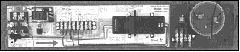
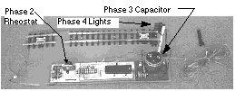
Figure 4 - Model 146b Control
Unit
|
Preparing Switch
Motor M3
11.
Preparing Switch Motor And Relay: The 12030
relay points (Item 12) snap into the end of
the 12010 switch motors (Item 11). There is a
plastic cover plate on the end of the motor.
Pry this cover plate off using a screwdriver,
and then snap the relay points into the end of
the switch motor.
12. Ream the
holes in left-rear and front-right feet of
the switch motor with a 7/64" drill.
NOTE:
As
an alternate to screwing down the switch
motor, if you don't want disturb the threads
in the plastic feet, you can drill 9/64"
holes in the wood base, and use wire to tie
the plastic feet to the base.
Drilling Holes
and Attaching Parts
13.
Drill 5/64 pilot holes in the wood control
unit base, for the knife switch, light bulb
base, terminal block, and switch motor.
NOTE:
You
can later disconnect the light bulb, or omit
it entirely, if you are planning to add
signal lights.
The purpose of
the light bulb is to verify the control is
receiving AC power. The signal lights will
verify presence of power also.
14. Screw
these parts to the wood base by using #4 x
5/8" long wood screws (Item 29).
15. Holes for
Wing Nuts and Screws: Drill two 3/16" holes
in the base. These holes are for the screws
and wing nuts used to attach the base to the
track unit. Note the template shows you a
set of crosshairs for the wing nut hole
location at the right-rear end of the base.
- Refer to
Sheet 4 Track Unit Assembly for the location
of the left-front hole, since it is off the
template.
|
7.
Connect
Wires - Control Unit -- Phase 1
Note that
we are using the template we made from the Phase
2 diagram, that we now have glued on the wood
base. But we are using the Phase 1 diagram as a
guide for the following steps.
In Phase 1 we
will build a "bare bones" basic unit. Thus we
will not use all the wires shown on the
template for Phase 1. Later we can add the
rheostat and additional wires to make the
Phases 2, 3, and 4.
Construction Notes
- You can strip
about 1/4" of insulation off the ends of
wires that connect to switch motors and
relay points. -- that is, where you are
sliding the end of the wire into the small
hole.
- When
stripping insulation off the ends of wires
that connect to terminals, you can strip off
about 1/2".
- When
connecting wires to terminals, you can use
the spade connectors (Item 51) to make a
neater attachment.
- You might
want to experiment with the procedure of
hooking up one end of the wire, then using
pliers to bend sharp corners to follow the
path on the template fairly exactly to
achieve a neat installation -- depending on
how fussy you want to be.
Attaching the
Wires
Use Sheet
9, Phase 1 Control Unit -- Starter Version,
as a guide for the following steps -- don't look
at Phase 2 yet.
16. Black
Wires: Connect BLACK wire L3 (prefix
L=BLACK) using 18 gauge solid wire (Item 20).
Black wire is
used for DC + that is "switched" -- that is,
sometimes the power is on, and sometimes the
power is off. (DC - on the right rail is not
connected to the control unit at all.)
17. Blue
Wires: Connect BLUE wires B2 and B99
(prefix B=BLUE) using 18 gauge solid wire
(Item 21).
Blue wire is
used for DC + that is "unswitched" -- that is,
the power is always on.
18. Green
Wires: Connect GREEN wire G2 (prefix
G=GREEN) using 18 gauge solid wire (Item 23).
Green wire is
used for AC + that is "switched" -- that is,
the power is momentarily on if the
corresponding track contact is activated, but
is normally off.
19. Red
Wires: Connect RED wires R2 and R11
(prefix R=RED) using 18 gauge solid wire (Item
24).
Note wire R3 is
the wire coming from the light, Item 82. For
this wire, you can just shorten the wire that
comes attached to the light and use that.
Red wire is used
for AC - (common).
20. Yellow
Wires: Connect YELLOW wires Y1 and Y16
(prefix Y=YELLOW) using 18 gauge solid wire
(Item 25).
Note wire Y3 is
the wire coming from the light, Item 82. For
this wire, you can just shorten the wire that
comes attached to the light and use that.
Yellow wire is
used for AC + that is "unswitched" -- that is,
the power is always on.
Conclusion:
At this point, the Phase 1 assembly of the
control unit should be complete.
|
8.
Assembly
Steps - Track Unit
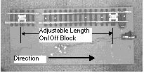
Figure 5 -- Model 146b Track Unit
|
Attach Track To
Base
Refer to
Sheet 4, Track Unit Assembly, for the
following steps.
21. Position the
loose track on top of the wood base.
22. Verify for
both 10153's (Item 48), the gap is in the left
rail
- Verify you have
not forgotten track contact T1.
23. With the
track in position, use a 5/64" drill to
drill holes through the plastic ties and
into the wood base.
24. Attach the
frontmost 2 pieces of track using #4 x 5/8"
long wood screws (Item 29).
Leave the
rear 10153 single isolating track
unattached. This can disconnected,
moved to the rear, and more track inserted
in-between, to make the length of the stop
block as long as necessary.
Attach Control
Unit to Track Unit
25.
Position the control unit on the corner of the
track unit, and drill two 3/16 holes to match
the holes in the control unit.
26. Using the 2
wing nuts and screws (Item 28), attach the
control unit to the track unit.
Connecting Wires
On Track Unit
For the
following steps, use a 9/64 drill to drill holes
through the wood base as required, in order to
run the wires underneath.
27. Black Wires:
Connect
BLACK wire 7.
NOTE:
Black
wire 3 does not get attached until later when
you add the slowdown circuitry in Phase 2.
28. Blue
Wires: Connect BLUE wire 8.
29. Green
Wires: Connect GREEN wires 9 and (after
reading below) 12.
30. Yellow
Wires: Connect YELLOW wires 10 and
(after reading below) wire 11.
Option: Use
Stranded Wire For Wires 11 & 12
On Sheet
04, Track Unit Asembly, the two wires 11
and 12 are shown as yellow and green
respectively. If T2 is going to be permanently
located in one place, then use the solid yellow
and green wire as described in the previous two
steps, so you have the color coding.
However, if you
plan to move track contact T2 a lot, you may
want to use the stranded wire instead of solid
wire. If you want to use stranded wire,
substitute the following 2 steps for the
previous 2 steps.
31. Using the
double-conductor 18 gauge stranded wire (such
as Radio Shack 278-1301 or similar), attach
the darker conductor (substituting for green)
to terminal 12 on the terminal block. Connect
the other end to the front-most terminal of
track contact T2.
32. Using the
same double-conductor wire as the previous
step, attach the lighter conductor
(substituting for yellow) to terminal 11 on
the terminal block. Connect the other end to
the center terminal of track contact T2 as
shown.
Connecting AC
Power
Make sure
you read the comments about voltage in
Increasing AC Control Voltage in the previous
section.
The power input
is via terminals 17 and 18 on the center of
the knife switch. Connect these to the AC
terminals on your power pack.
OPTION: You can
connect input power using a female RCA phono
plug for a quick connection. This is shown in
the following figure, Using Phono Jack
Wire For Input AC Power.
You can use a
Radio Shack #42-2449 or similar; and cut it
into a piece about 1 foot long and a 2nd piece
about 11 foot long. You can put spade
terminals on the cut end of the 11-foot piece
to connect to the transformer. The other end
has a male phono plug, with a connector, will
quickly connect to the male phono plug of the
1-foot piece connected to the control unit.
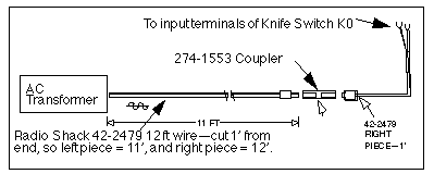
Figure 6 - Using Phono Jack Wire
For Input AC Power
|
What To Do Next
At this
point, you have completed the assembly of the
bare-bones Phase1 block. The next section tells
you how to operate this unit, plus instructions
to add the additional parts to build Phases 2, 3
and 4.
|
|