Model 205, 2-Track Yard (Largescale) |
|||||
-
|
superseded by the Model 206 Control Unit. |
||||
1.
Related
Pages (access w/links in menu at
left)
|
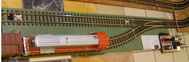
The following
figure shows the completed Model 165,
2-Track Automatic Switching Block.
2.
Summary
The
2-track yard is the "next step" up from the
single-track block. This yard can control a
minimum of 3 trains on 1 loop, by holding 2
trains in the yard while the 3rd is travelling
the mainline. Sometimes 4 or more trains can
be controlled on the loop, if the trains run
similar speeds and the loop is large.
Figure 1 - 2-Track Automatic Switching Block
assembly